The superconducting magnets and cryopumps in the ITER needs to be cooled down to around 4 K (-269 C) for their efficient operation. Those are surrounded by 80 K thermal shields to minimize heat load. The cryogenic system for cooling of magnets and cryopumps is mainly divided in to three sub-systems as (a) cryoplant (b) cryolines and warmlines (c) cryo-distribution system.
While the 4 K helium cryoplant is directly procured by ITER Organization (IO), liquid nitrogen and 80K helium plants are procured by Fusion for Energy (European Domestic Agency). The cryo-distribution system as well as cryolines and warmlines are supplied by Indian Domestic Agency via ITER-India.
Cryo-distribution and Cryolines (CDCL)
Cryo-distribution: The Cryo-distribution system consist of 8 cold valve boxes as follows.
- Cryoplant Termination Cold Box (CTCB): It connects three helium cold boxes (25 KW at 4 K each), liquid helium storage tank as well as 80 K plant to five auxiliary cold boxes and thermal shield cooling system inside Tokamak building via complex system of cryolines and warmlines.
- Auxiliary Cold Boxes (ACBs, 5 number): It consist of many valves, heat exchangers, cold circulators and cold compressors. ACBs establish complex link between application (superconducting magnets and cryopumps) side closed cryogenic loop with source (cryoplant via CTCB) side cryogenic loop.
- Thermal Shield Cooling System (TSCS): TSCS consist of Thermal Shield Cold Valve Box (TCVB) and Manifold Box (MB). TCVB channelizes 80 K gas helium from 80 K helium plant (via CTCB) to 8 individual flow passages of thermal shields inside cryostat of tokamak machine and collects return helium gas to be send back to 80 K plant via CTCB. Manifold Box is a major connection point between TCVB and ITER cryostat.
Image
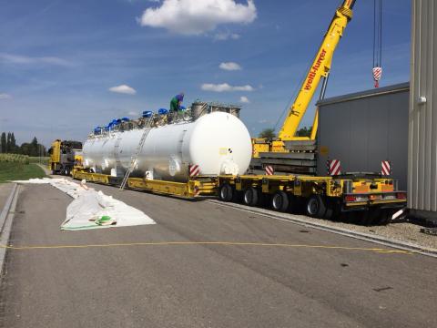
Figure 1: CTCB Transport from Manufacturing Site to ITER Site, Q1-2019
Image
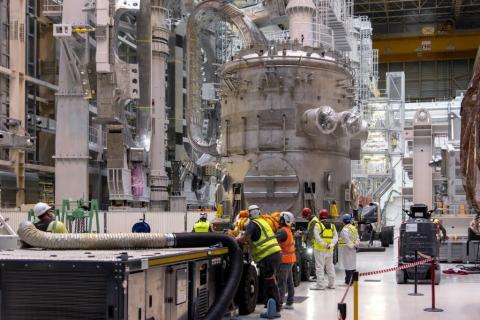
Figure 2: ACB-1 at ITER Site (B13), Dec-2023
Cryolines and Warmlines
The 10 km long complex network of ITER cryolines and warmlines consist of roughly 5 km of vacuum jacked cryolines and 5 km of warmlines. ITER-India initiated the procurement phase as early as 2012 with design, manufacturing and testing of vacuum jacketed prototype cryolines (1:1 scale in diameter, 27 m long) consisting of six process pipes and hard thermal shield.
CDCL R&D
Development of Helium Cold Circulator for ITER
Cold circulators are used to maintain flow of Supercritical Helium (SHe) in superconducting magnets and cryo-pumps panels. For the ITER project, due to massive sizes of superconducting magnets and cryopumps, two prototypes of world’s largest SHe cold circulators (up to 3 kg/s of SHe and 1.5 bar pressure head) are developed by ITER-India with its industrial partners and successfully tested at JAEA test facility in Japan in 2016.
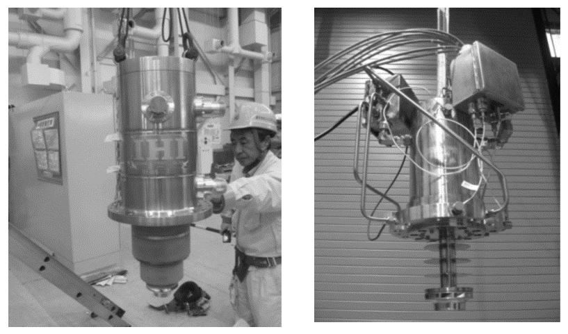
Figure 3: Both Prototypes of Cold Circulators
ITER-India Cryogenics Laboratory (IICL)
ITER-India has successfully established cryogenic laboratory cum test facility for testing of cryolines at 4 K and 80 K temperature levels. The two prototypes of multi-process cryolines (called PTCL-1 and PTCL-2), designed and manufactured by two different vendors with deep involvement of ITER-India technical team, was exhaustively tested at room and cryogenic temperatures at IICL. The comprehensive room temperature tests mainly included helium leak tests and pressure tests (as per European Pressure Equipment Directives) while the cryogenic tests included measurement of thermal profiles, heat loads, Break of Insulation Vacuum Tests, strain measurement etc. at cryogenic (80 K / 4.5 K) temperatures.
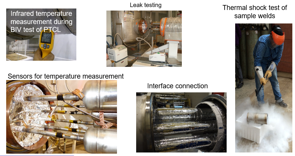
Figure 4: Various Activities/Tests Carried Out on PTCL at IICL
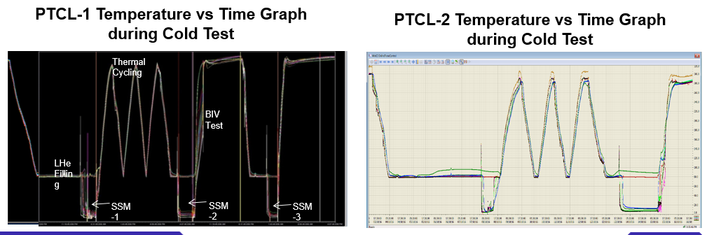
Figure 5: PTCL Cold Test Graphs
Timeline - IICL
2010
Planning for the development of test facility at IICL
2012
Finalized the design of 4.5 K and 80 K system and Procurement of the systems started
2014
Made test facility
2015
Tested first prototype cryoline
2016
Tested second prototype cryoline
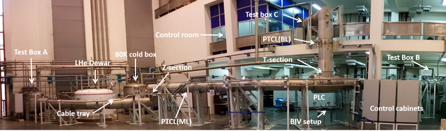
Figure 6: First PTCL at IICL (2015)
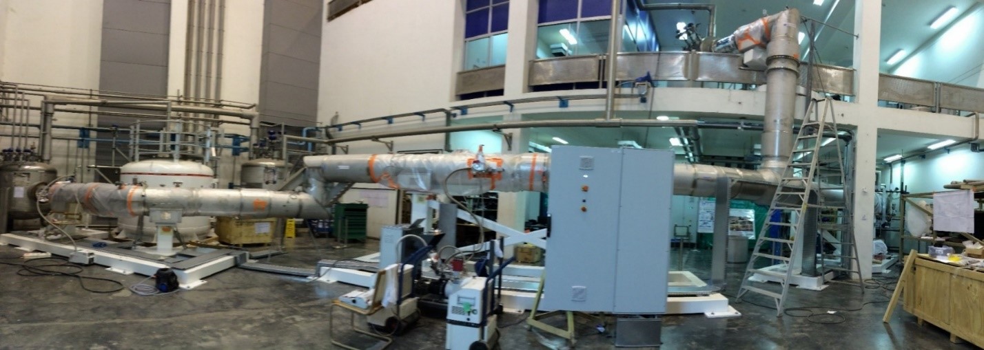
Figure 7: Second PTCL at IICL (2016)
Main Features of the IICL
The lab mainly consists of following systems
- 4.5 K vapor helium system: A vapor helium is taken from the 5000-liter liquid helium Dewar using in-built heater. The helium vapor flow can be controlled at around 0.5 g/s, 1.1 bar(a). After use, the return helium is warmed to the room temperature using heaters and recovered in helium storage tanks of IPR.
- 80 K helium system: A closed loop system consist of room temperature helium gas tank from where helium is taken, compressed in helium compressor, cleaned in purifier to remove impurities, cooled using liquid nitrogen in heat exchanger, and supplied to the client. The return helium gas (typically less than 90 K) is send back to heat exchanger to economize the cooling / warm-up operations, and almost room temperature helium exiting from the heat exchanger is send back to the compressor suction.
- Auxiliaries: The lab also includes air compressor for instrument air, liquid nitrogen storage tank, control room with SCADA, PLCs, etc.
Image
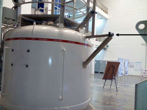
Figure 8: 5000 Liter liquid helium Dewar
Image
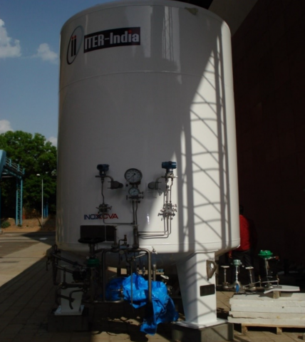
Figure 9: 6000 Liter Liquid Nitrogen Tank
Image
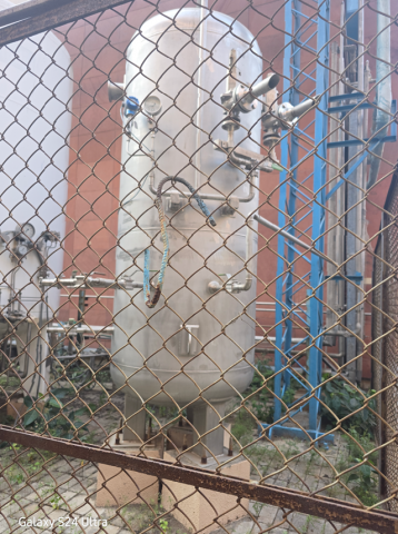
Figure 10: Helium Gas Buffer Tank
Image
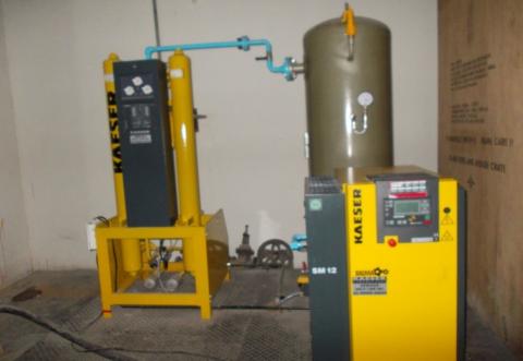
Figure 11: Air Compressor for Instrument Air
Image
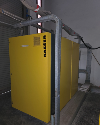
Figure 12: Compressor for Helium Gas
Image

Figure 13: 80 K Helium Generation Cold Box