Introduction
Diagnostics are eyes and ears of tokamak machine, and plays important role in plasma characterization, plasma control, machine protection. ITER-India is responsible for design, develop and delivery of four diagnostics systems and a port plug and integration of one diagnostic Upper Port -09 (UP-09).
IN-DA Diagnostics:
- Electron Cyclotron Emission (ECE) Diagnostics : How Hot Are ITER’s Plasma Electrons?
- Charge Exchange Recombination Spectroscopy (CXRS–Pedestal) : Measuring Ion Temperatures at the most crucial pedestal region.
- X-Ray Crystal Spectroscopy (XRCS–Edge) : Revealing How Hot the Ions Really Are at the ITER Edge
- X-Ray Crystal Spectroscopy (XRCS–Survey) : Identifying the Major Impurities of ITER’s Plasma
The ECE and XRCS Survey diagnostic delivery is scheduled for Start Research Operation (SRO) phase whereas CXRS and XRCS-Edge are for DT plasma along with UP-09.
Electron Cyclotron Emission (ECE)
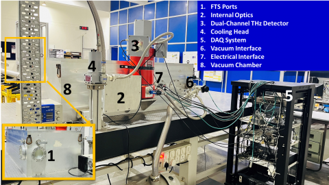
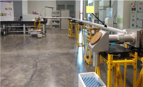
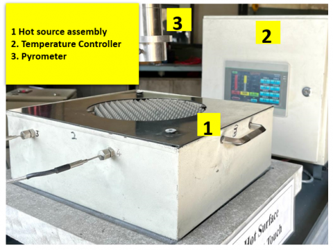
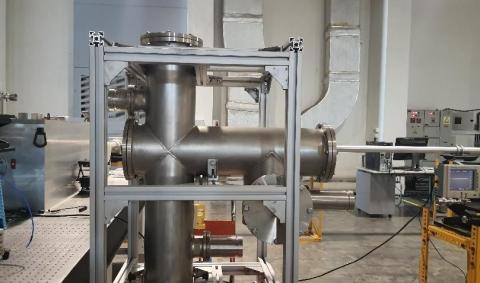
The ITER ECE diagnostic system provides electron temperature profiles of the plasma. It comprises front-end optics with an in-situ 1000 oK hot calibration source, a polarization splitter unit for selecting O-mode and X-mode emissions, and four transmission lines that deliver the radiation to radiometers and Fourier Transform Spectrometers (FTSs) located in the ITER Diagnostics Hall. The system includes an in-lab calibration source, two broadband FTS units (70–1000 GHz), an low frequency radiometer (122–230 GHz), and an high frequency radiometer (230–344 GHz). The front-end optics, including the hot source and the high frequency radiometer, are under the US-DA scope, while the remaining components are under the IN-DA scope. A prototype system developed by IN-DA includes an 8 m transmission line (72 mm diameter), a hot calibration source operable up to 650 °C, and an FTS covering 70–1000 GHz with 10 GHz spectral resolution.

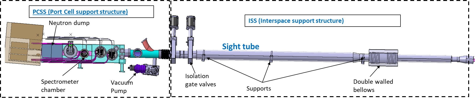
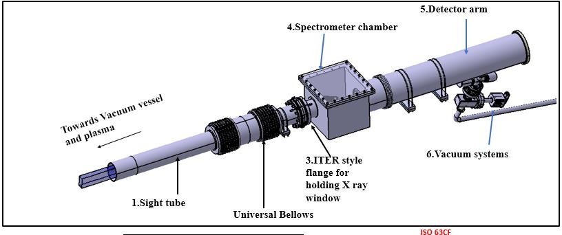
XRCS-Survey Spectrometer
A broadband X-ray spectrometer (1-22 Å/ 0.5 keV-12 keV) which measures X-ray radiation from various intrinsic impurities such as W, Fe, Cu and externally injected impurities such as Ar, Ne and Xe for impurity detection and machine protection. The spectrometer is comprising of nine novel cubic shaped X-ray crystals along with four X-ray detectors (one hybrid photon counting detector and three CCDs to cover the entire energy range). The spectrometer is designed in such a way that it captures emissions from all these impurity lines radiations, simultaneously. The X-ray emissions from the ITER plasma are transported via 12-meter vacuum extension connected to the closure flange at the Equatorial port 11. The wavelength and intensity calibrations will be performed using X-ray sources of different targets.
XRCS-Edge Spectrometer
A high-resolution imaging type of X-ray spectrometer for measurement of edge ion temperature. The spectrometer will probe the edge plasma impurity emissions of Argon species in the wavelength region of ~ 4 Å. The spectrometer is situated in upper port -09, consists of a double‑reflection optics with toroidal graphite and spherical quartz crystals placed in Rowland mount configuration. The emission spectra are recorded with a large area hybrid photon counting detector. The X-ray emissions are coupled to the spectrometer using a ~3m vacuum extension tube from closure flange of upper port 9.
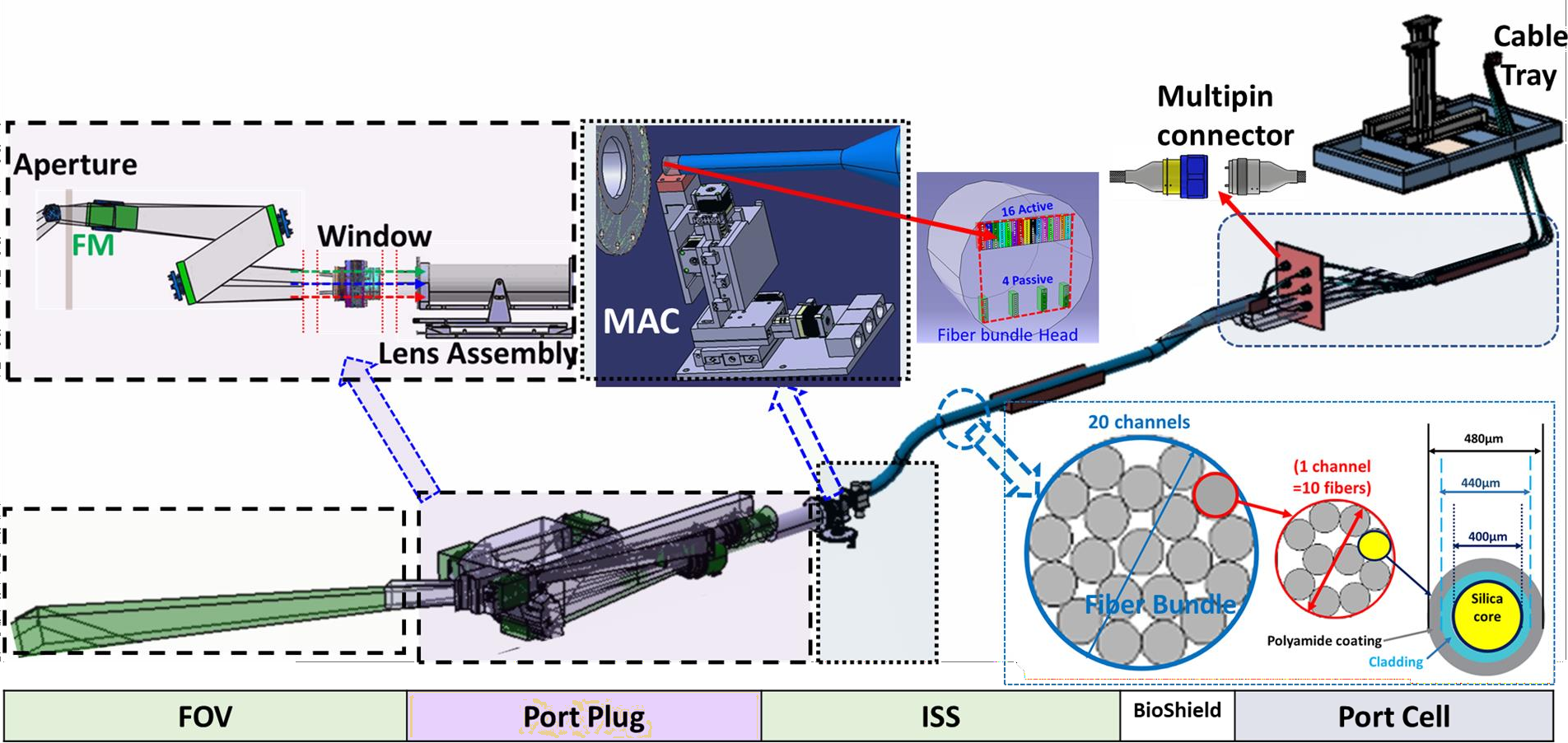
CXRS-Pedestal Diagnostic
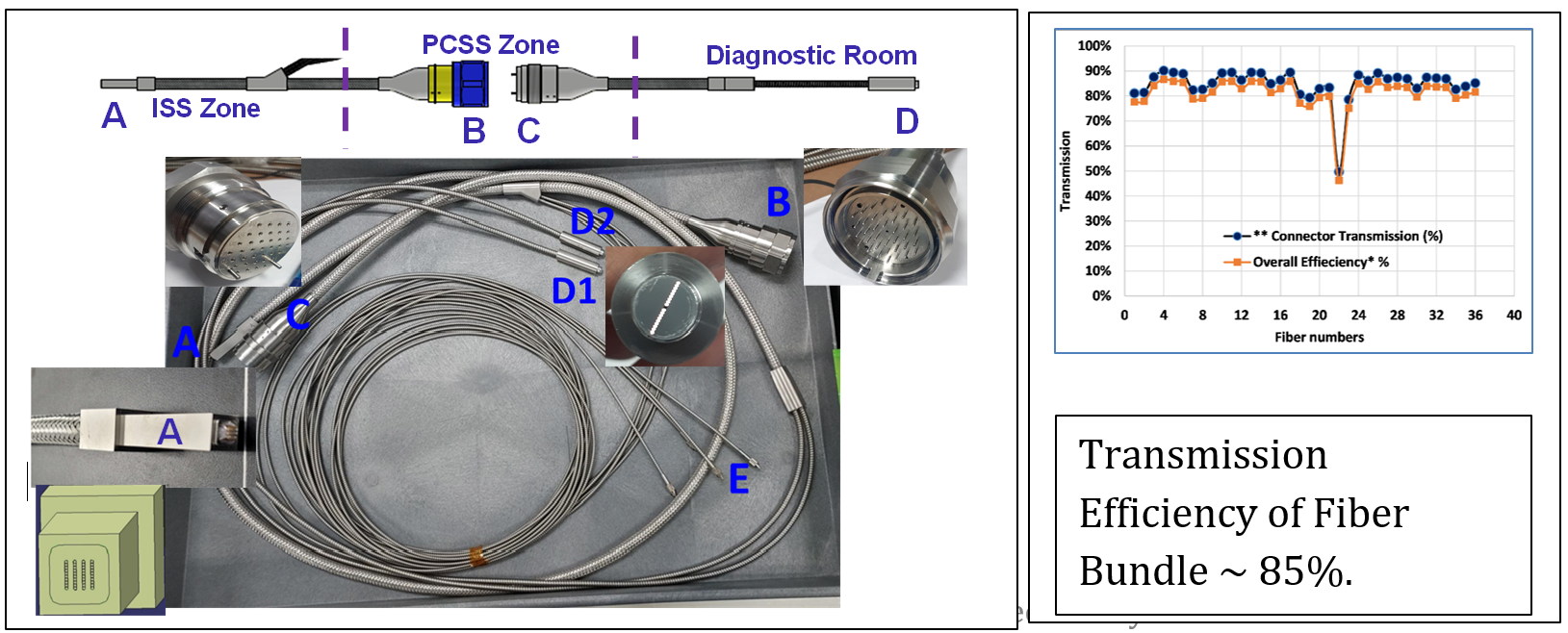
This diagnostic provides ion temperature and plasma rotation at the pedestal region (ρ > 0.85). This diagnostic view the pedestal region of the diagnostics neutral beam (DNB) plasma interaction zone and collects the charge exchange emissions of He, Ar and Ne and beam emissions from hydrogen DNB. The emissions are collected via optical labyrinth situated inside Equatorial port -3 and transported to the visible spectrometers using radiation resistant fiber optic bundles. The CXRS spectrometers are one of its kind having a customized design to measure three wavelengths, simultaneously. Developments include high-transmission radiation hard fiber bundles (> 82 %), a magnetic resilient and radiation resistant Misalignment Compensator (MAC) and High Etendue Visible Spectrometer are under progress.
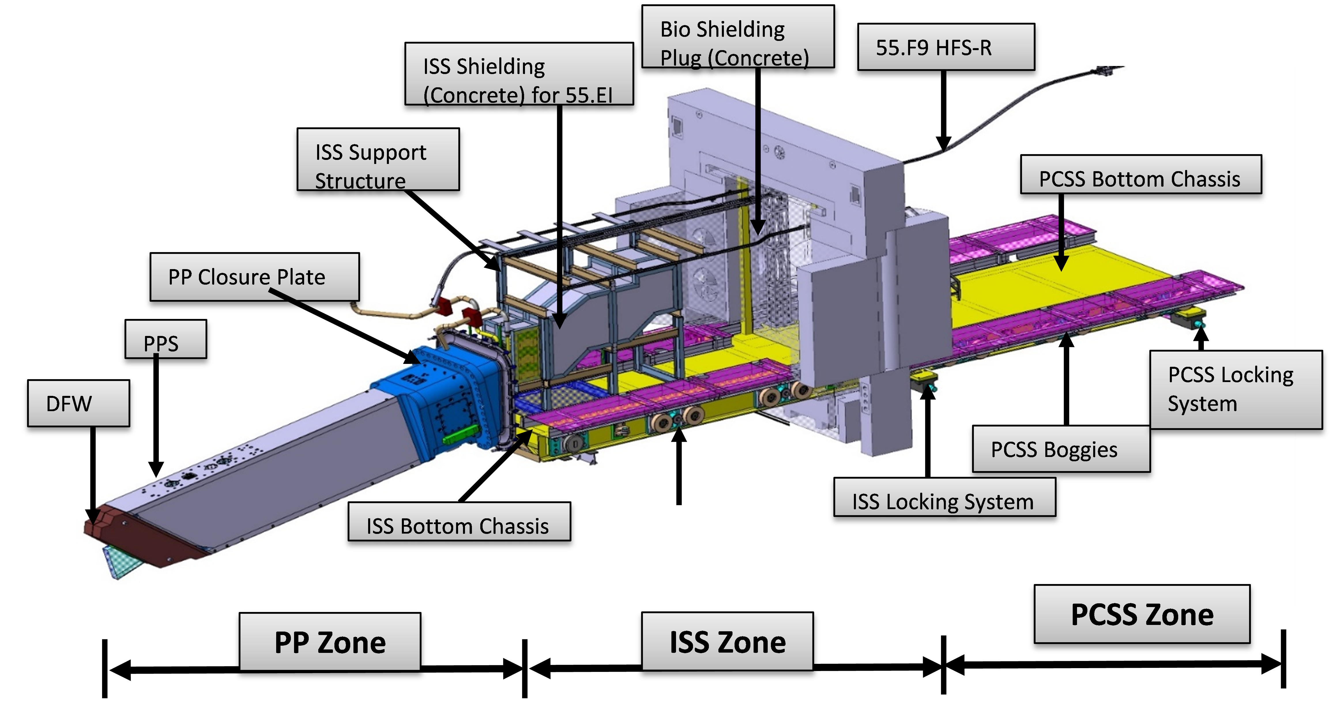
Upper Port Plug-09 (UPP)
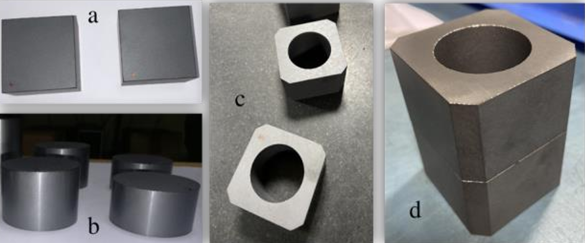
The upper port -09 hosts two tenant diagnostics: XRCS-Edge spectrometer and High Field side Reflectometer (HFSR)waveguides. The port plug design caters to the need of providing line of sight for the X-ray spectrometer and also HFSR. The neutron shielding blocks used in port plug are made up of B₄C blocks. As a protype activities these B4C blocks are developed along with Indian industry: M/s Bhukanvala, Gujarat.
Fourier Transform Spectrometer (FTS), Transmission line, Hot Source and polarization splitter of ECE diagnostic system
CXRS -P ‘s prototype 40 channel Fiber Bundle Assembly
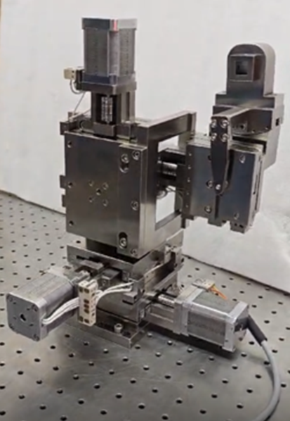
Specifications of MAC
| Parameter | Value |
|---|---|
| Linear Travel Range | ± 24mm |
| Angular Travel Range | ±5° |
| Resolution for Linear Travel | 40µm |
| Resolution for Angular Travel | 10µrad |
| Load Compatibility | ~ 3 Kg |
| Compatible for Magnetic Field | ~ 300mT |
| Neutron Flux | ~ 1x10 13 neutron/ m2 s |
Magnetic Resilient Radiation Resistant 4 axis stage
(Misalignment Compensator MAC)
UPP-09 B₄C Shield Blocks
Challenges & Risks
- First of Kind instruments Harsh nuclear environment (neutron/gamma radiation)
- Static magnetic field ( ~ 300 mT)
- Radiation shielding
- Stringent alignment requirements
- Interface and integration complexities
- Long time operation with I & C
Industrial Partners
- BluSky Spectroscopy – Dual Channels fast scanning Fourier transform spectrometer
- Holmarc, New Age Instruments and Materials –Mechanical Alignment Compensator (MAC) for CXRS
- New Age Instruments and Materials and Fiberguide industries (Molex) - Fiber Bundle Assembly
- Bhukhanvala Industries Pvt.– B₄C shielding material
- Dectris – Hybrid photon counting detectors and CCDs.