Outline
ITER being an experimental device, the heat generated out of fusion reaction in ITER machine will not be used to produce electricity. It will rather be rejected to the environment with the help of massive but high-performance Cooling Water System (CWS). ITER’s Cooling Water System is designed to manage all heat generated during the operation of Tokamak machine and auxiliary systems. Demineralized water is utilized to remove heat from plasma received at the vacuum vessel and its components and to cool auxiliary systems such as the radio frequency heating and current drive systems, the neutral beam systems, the cryogenic system, the coil power supply & its distribution system and the HVAC systems of various buildings on the site. The CWS incorporates multiple closed loops that all transfer heat to the heat rejection system which ultimately rejects all the heat to the environment using induced-draft cooling towers.
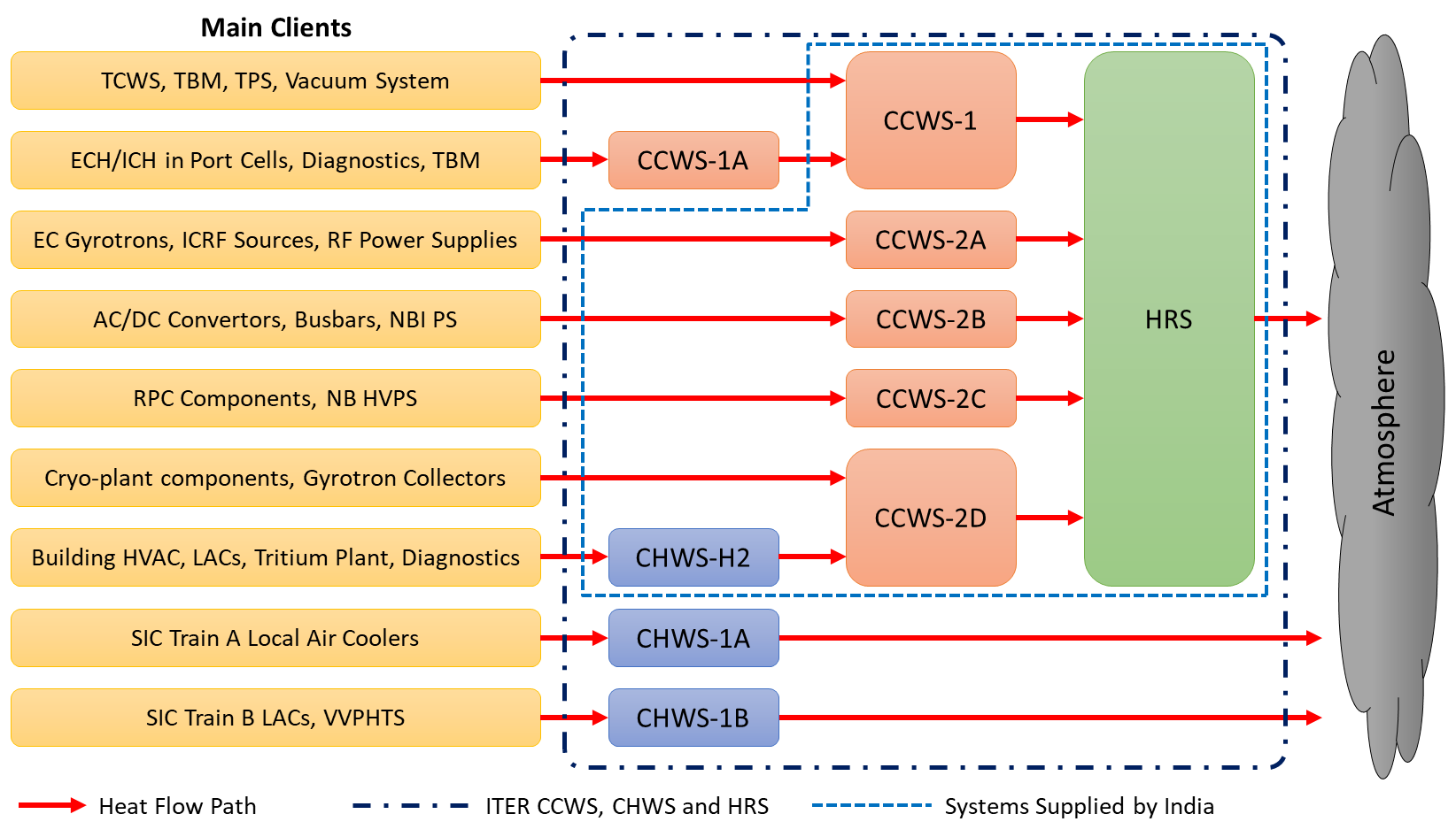
The heat generated in the plasma is transferred through the Tokamak Cooling Water System (TCWS) which includes several Primary Heat Transfer (PHTS) loops and supporting systems such as baking loop, draining & drying systems, and chemical & volume control systems. The overview of ITER CWS is shown in fig-1 below
Key design features
The tokamak will operate in cyclic mode with a cycle typically containing a plasma burn phase for 1/4th of the cycle time followed by a dwell period for remaining 3/4th of the cycle time. A peak of about 1000 MW of heat will be produced in tokamak during the plasma burn phases. The auxiliary systems will produce more than 150 MW of heat continuously during the entire operation. The CCWS and CHWS are designed to transfer all of the heat produced immediately to HRS while the HRS is designed to dissipate heat to atmosphere at an average rate of 510 MW. Excess heat received during plasma burn phases is stored in HRS’s hot water basin which acts as a thermal buffer allowing continuous operation of HRS at the average capacity. The design was required to comply severe meteorological conditions (-25oC & +45oC) and seismic requirements.
Key accomplishments
The route from design to engineering, manufacturing, procurement and testing of the components and system as a whole followed the concept and functional specifications of the system provided by ITER organization. Most of the components and related sub-assemblies were manufactured in India across different locations and included the involvement of several contractors/ sub-contractors/ manufacturers. The design, manufacturing and testing of the supplied components followed the stringent quality norms applicable to ITER nuclear establishment.
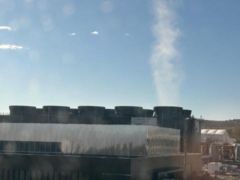
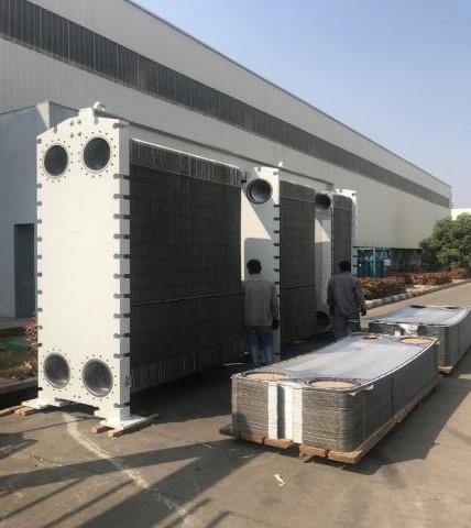
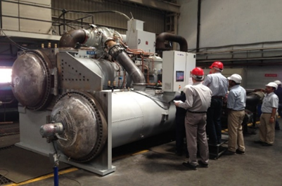
CCWS, CHWS and HRS incorporate some of the biggest equipment available in the market such as pumps with 1.87 tons/s flowrate, vertical turbine pumps with 1.4 tons/s flowrate, electric drives with 1.4 MWe power rating, variable frequency drives of 6.6 kV/ 750 kW for controlling speed of pumps, plate type heat exchangers with 70 MW heat exchange capacity, water-cooled centrifugal chillers with 1150 TR capacity, soft starters of 6.6 kV/ 800 kW capacity, induced draft cooling towers made of FRP with a total ~510 MW of capacity (dimensions 80m (L) X 32m (W) x 20 m (H)), pressurizer tanks, water polishing units in CCWS loops to maintain ultra-pure (electrical conductivity ≤ 0.3 µS/cm; DO2≤ 50 ppb) chemistry of circulating water, Ozone generation plant to control micro-biological growth in HRS water, modular E-house (21 m (L) X 7 m (W) X 4 m (H)) to house electrical components, 1400 nos. of valves (different types and sizes), cables of ~61 km length, various instruments, stop log gates, bellows, strainers, panels, heat tracing components, plant control system, cubicles, etc. Overall electrical power consumption stands close to 40 MWe for simultaneous operation of all systems. Cooling water distribution network, with more than 18 km of piping and up to 2m diameter, supplied as 4500 spools involving one lakh inch-dia welding and supported by 900 MT of steel supports, expands across the site serving various buildings.
Contributions from Industries
The supply of CCWS, CHWS and HRS is one of the significant and important contributions from India to ITER. It could not have been achieved without the collaboration and active participation of Indian domestic industries. While the preliminary design was advanced by M/s Engineers India Limited, followed M/s Tata Consulting Engineers, the final engineering and procurement was executed by M/s L&T Construction. The components were sourced from major manufacturers across India such as M/s Kirloskar Brothers Ltd for pumps, M/s Kirloskar Chillers Pvt Ltd for Chillers, M/s Kirloskar Electric Co. for motors, M/s Paharpur for cooling towers, M/s Kelvion for plate heat exchangers, M/s Ratnamani for pipes, M/s Jindal for steel structures, M/s Forbes Marshall, M/s Intervalve Poonawala, M/s L&T Valves, M/s NSSL and M/s R&D multiples for valves, M/s ABB for VFDs, M/s Gujarat Infrapipes Private Limited for pipe fittings, M/s Baroda Equipment & Vessels Pvt Ltd for Pressurizers, M/s Filtration Engineers India Pvt Ltd for strainers & filters, M/s General Instruments for instruments, M/s KEI industries for cables, M/s Macmet Engineering Ltd for stop-log gates, M/s Xicon for heat tracing, etc. to name a few. All manufacturing activities strictly adhered to various quality and safety norms in place. The equipment have been manufactured complying to applicable European directives.
Present status
The construction/installation of India-supplied systems started at ITER site in the year 2018. The systems have been already fully installed, commissioned and in operation. The HRS cooling towers rejected first heat loads to atmosphere from Cryo-plant operation in April 2024 and has been in continuous operation.
ITER-India has recently started the prototyping of safety-important valves required for safety isolation.
Currently, ITER-India has signed another agreement with ITER to design and supply new loops, namely CCWS-2F and CHWS-H4, that were recently introduced in ITER’s baseline. The goal is to complete the design in 2026 and manufacture and supply all components by the end of year 2029.
Timeline and Milestones
Pictures from manufacturing phases
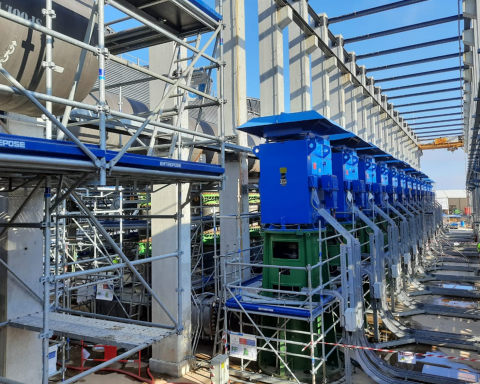
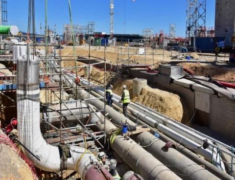
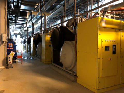
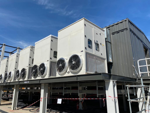
Pictures from construction site